Here everything about the parts of a wireless cell phone charger including their names and functions:
- Nonslip pad surface
- Chipset
- LED indicator
- Input DC rail
- Transistor bridge
- Transmitting coil
- Thermal protection sensor
- Foreign object detection circuit
- Receiving coil
- Battery
So if you want to learn all about the parts of a wireless cell phone charger, then you’re in the right place.
Let’s get started!
- Cell Phone Charger Parts: Names & Functions?
- Mechanical Keyboard Switch Parts: Names & Functions?
- Mechanical Keyboard Parts: Names & Functions?
- Vape Mod Parts: Names & Functions?
- Laptop Charger Parts: Names & Functions?
What Are the Parts of a Wireless Cell Phone Charger?
Wireless charging has become very common in the past few years, and for a good reason as well.
Wireless phone chargers offer less hassle compared to their wired counterparts. Learn all about the parts of ordinary cell phone chargers here.
You don’t have to worry about tangling wires and what kind of connector works with what device.
Wireless chargers don’t need special connectors.
As long as the smartphone itself supports wireless charging, any wireless charger will work.
So, what makes this science fiction-esque technology possible?
This article will go through all of the main components inside a wireless cell phone charger and see what they do.
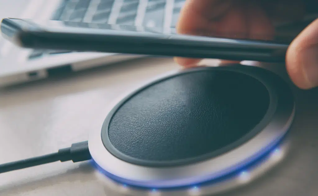
#1 Nonslip Pad Surface
The nonslip pad surface on the wireless charger is a physical interface that your cell phone and the wireless charger interact at.
Nonslip surfaces on wireless chargers are designed so that you can put your phone on this surface without any worry.
As long as the cell phone is on top of the surface, it will charge your phone.
Most of the time, this surface is easier rubberized or uses some kind of anti-slip plastic surface.
It would be a shame if you placed your cell phone on a wireless charger, and it slips and breaks your screen.
So most modern wireless chargers come with special surfaces to hold your phone in one place.
Underneath the surface is the main coil that is electromagnetically charging your device.
#2 Chipset
The chipset inside the wireless cell phone charger can greatly vary depending on the type and the company making the wireless charger.
Generally speaking, the main function of the chipset on the wireless charger is to act as the brains of the operation.
The chipset controls how much current is being drawn into the wireless charger from the power outlet on the wall.
The chipset decides how much current needs to be sent through the coils to transmit the power required.
The wireless charger has to provide different power based on what brand of cell phone you are using.
For example, Apple’s iPhones charge 7.5 W, while a Samsung device charges 9 W.
All of the processing that is taking place on the wireless charger is being done via the chipset.
#3 LED Indicator
The LED module on a wireless charger is usually placed on the front of the charger.
Its primary function is to let the user know if the cell phone is charging or if the cell phone has been fully charged.
Some wireless chargers come with a LED, while other more expensive chargers may even have some display screens showing other data such as power draw and estimated time to charge.
The main purpose of this module is to keep the user informed about the current status of the charger.
#4 Input DC Rail
The input DC (Direct Current) rail on a wireless charger is typically either a 5 V or 19 V.
The AC/DC power adapter is usually connected to the wireless charger via a USB port.
Most current wireless chargers use a USB type C port. But some older wireless chargers will also have micro-USB ports.
The input rail is how the wireless charger is powered.
Electrical power is drawn from the adapter connected to the power outlet on the wall.
The current goes through some other circuits and is then fed into the transmission coils.
These transmission coils then induce a current in the receiving coils on the cell phone. This induced current is what charges the battery on the receiving cell phone.
#5 Transistor Bridge
The current from the input goes to a switched transistor bridge. This is the place where the resonant frequency is set internally by using series capacitors.
Once they set the current’s resonant frequency, these bridges will then supply the current to the transmission section of the wireless charger. This is an electromagnetic induction coil that transmits power wirelessly.
The receiving coil receives this power on the smartphone.
Some smartphones have coils that can act both as a transmitter and a receiver.
So, you can practically use that cell phone to charge other cell phones wirelessly.
A transistor bridge has two or four FETs.
FETs are Field-effect transistors, and their job controls the on/off switch at the transmission coil.
FETs also at the receiving end (i.e., the smartphone’s coils) also regulate on/off switching at that end.
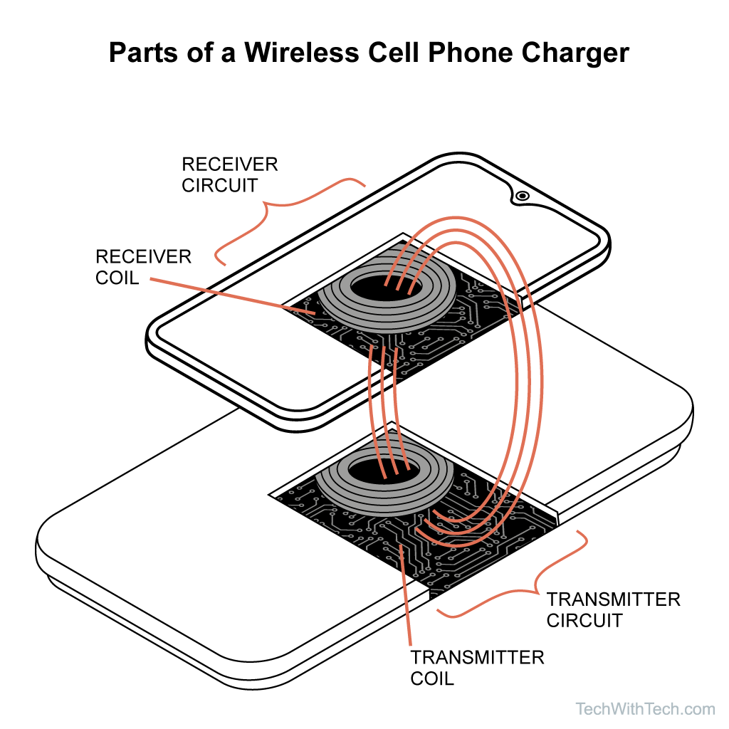
#6 Transmitting Coil
The transmission coil is the main component that actually transmits the power to the cell phone.
The coil works on a principle called electromagnetic induction or magnetic induction.
When current flows through a conductor, in our case, the coil generates a magnetic field around it.
If we vary the current flowing in the conductor, it also changes the magnetic field.
If there is another conductor nearby, such as the coil on the smartphone, then current can be induced on the secondary coil, even though the second coil isn’t physically touching the primary coil.
This principle is behind other important things like motors, electric generators, and actuators, etc.
But just recently, we have started using it as a way to charge devices like smartphones and smartwatches.
#7 Thermal Protection Sensor
Most wireless chargers also come with special thermal protection sensors. These sensors monitor thermal activity on the wireless charger.
They turn off the charging process as soon as they sense that the wireless charger’s temperature exceeds the safety level.
Heat is always generated whenever there is a flow of current.
And wireless charging produces more heat since a lot of current is flowing in the charger.
Sometimes the wireless charger can overheat if it is being used for too long.
Other times, it could be because the room’s ambient temperature is already high, and there is no effective heat transfer to cool the wireless charger.
Whatever the case, an overheating wireless charger can be dangerous.
But thankfully, all wireless chargers have redundancies built-in for this exact scenario.
As soon as the wireless charger nears the safety limits set by the manufacturer, the thermal protection sensor detects it and turns the wireless charger off. This protects both your wireless charger as well as your cell phone from any damage.
#8 Foreign Object Detection Circuit
As the name suggests, this circuit detects foreign objects.
But what are foreign objects for a wireless charger?
Well, they can be almost any conducting material.
This is because a charging coil can’t tell the difference between a smartphone’s coil or any other electrical conductor nearby, like a metal plate. So, without a foreign object detection circuit.
Wireless charging would start transmitting power to the metal plate. This can be dangerous since metal objects can very easily heat.
This is exactly how induction stoves work. So, a wireless charger heating up nearby conducting devices is not so great for the user.
To combat these problems, wireless charger manufacturers use foreign object detection circuits.
These circuits use a variety of authentication techniques to make sure they are transmitting power to a smartphone and not a piece of metal.
The following components may not be inside the wireless charger itself, but they are just as important to understand in regards to the wireless charging of a cell phone.
#9 Receiving Coil
The receiving coil is located inside the cell phone. This is the conductor that is designed to receive power via electromagnetic induction from the primary coil.
A lot of newer cell phones have coils capable of both receiving and transmitting power. This allows them to both be charged via wireless charging and charge other devices via wireless charging.
As the name says, the receiving coil receives the power in its coil via induction.
The current starts flowing in the circuit and is then directed towards the battery of the smartphone.
#10 Battery
The battery of a cell phone is how it stores its power.
Most cell phones use a lithium-ion battery pack.
Once the current is received from the coil of the smartphone, it is used to charge the battery.
Battery stores energy in the form of chemical potential.
During charging, electrical energy is converted into chemical potential energy.
The opposite happens during discharging.
Chemical energy is converted into a flow of electrons, more commonly known as current.
This current then powers all the circuitry inside the smartphone.
- Cell Phone Charger Parts: Names & Functions?
- Mechanical Keyboard Switch Parts: Names & Functions?
- Mechanical Keyboard Parts: Names & Functions?
- Vape Mod Parts: Names & Functions?
- Laptop Charger Parts: Names & Functions?